Logic Gates
| Gate | Symbol | Operator |
|---|---|---|
| Conjuction AND |
 |
∧ |
| Disjunction OR |
 |
∨ |
| Negation NOT |
 |
¬ |
| Exclusive Disjunction XOR |
 |
⊻ |
Q = ¬A ∨ (B ∧ C)
| Input A | Input B | Input C | D = ¬A | E = B ∧ C | Output Q = D ∨ E |
|---|---|---|---|---|---|
| 0 | 0 | 0 | 1 | 0 | 1 |
| 1 | 0 | 0 | 0 | 0 | 0 |
| 0 | 1 | 0 | 1 | 0 | 1 |
| 1 | 1 | 0 | 0 | 0 | 0 |
| 0 | 0 | 1 | 1 | 0 | 1 |
| 1 | 0 | 1 | 0 | 0 | 0 |
| 0 | 1 | 1 | 1 | 1 | 1 |
| 1 | 1 | 1 | 0 | 1 | 1 |
Logic Circuits
- Made up of a series of logic gates to create full systems
- Could be thousands of gates
- The output from the first gate becomes the input for the second gate and so on
e.g. Simple alarm system
A or B = 1 means that the sensors have picked up an intruder A or B = 0 means that the sensors have not picked up an intruder C = 1 means the override button has been pressed to turn the alarm off C = 0 means the alarm will continue to sound
Q = (A ∨ B) ∧ ¬C
| A | B | C | Q |
|---|---|---|---|
| 0 | 0 | 0 | 0 |
| 1 | 0 | 0 | 1 |
| 0 | 1 | 0 | 1 |
| 1 | 1 | 0 | 1 |
| 0 | 0 | 1 | 0 |
| 1 | 0 | 1 | 0 |
| 0 | 1 | 1 | 0 |
| 1 | 1 | 1 | 0 |
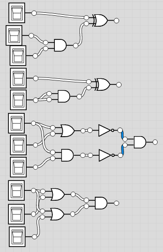
Q = (A ∧ B) ∧ (C ∨ D)
Q = (¬A ∨ (A ∧ B)) ∨ C

Q = ¬((A∧B) ∨ ¬(A∧C))
| A | B | C | Q |
|---|---|---|---|
| 0 | 0 | 0 | 0 |
| 1 | 0 | 0 | 0 |
| 0 | 1 | 0 | 0 |
| 1 | 1 | 0 | 0 |
| 0 | 0 | 1 | 0 |
| 1 | 0 | 1 | 1 |
| 0 | 1 | 1 | 0 |
| 1 | 1 | 1 | 0 |